9 Results
View results:
Sort by:

The dynamic analysis in RFEM 6 and RSTAB 9 is divided into several add-ons. The Modal Analysis add-on is a prerequisite for all other dynamic add-ons, since it performs the natural vibration analysis for member, surface, and solid models.
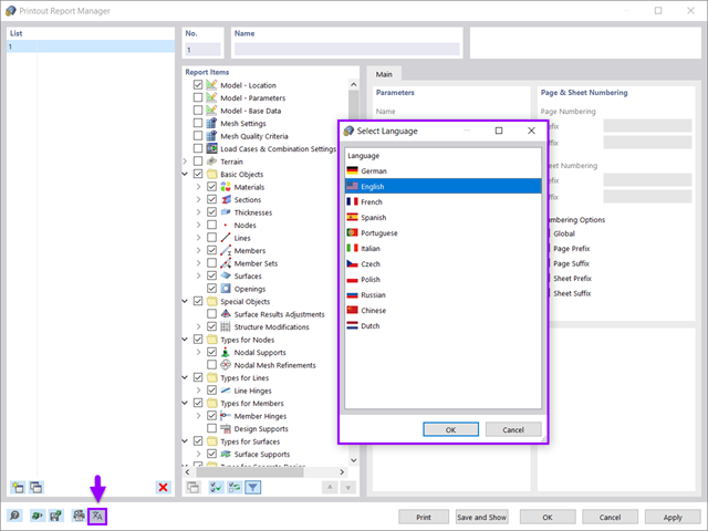
All data in RFEM 6 can be documented in a multilingual printout report. The design of the printout report is modern and has been highly optimized with respect to the previous (RFEM 5) generation of the program. Some of its most significant features are discussed in this article.

The new generation of RFEM software is an intuitive, powerful, and easy-to-handle 3D FEA program that meets all the latest demands in modeling, calculation, and structural design. The modern design concept, as well as the introduction of new features, make the program even more innovative and user-friendly. The main differences between RFEM 6 and its previous version, RFEM 5, are discussed in the following text.
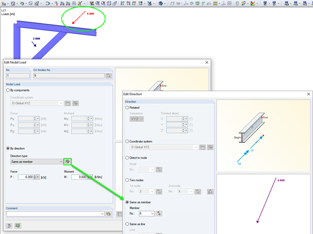
RFEM and RSTAB provide various options for entering nodal loads. These implemented features allow the user to define the nodal loads in relation to different components in space.

Closed circular cross-sections are ideal for welded truss structures. The architecture of such constructions is popular when designing transparent roofs. This article shows the special features of the connection design using hollow sections.

Different methods are available for calculating the deformation in the cracked state. RFEM provides an analytical method according to DIN EN 1992-1-1 7.4.3 and a physical-nonlinear analysis. Both methods have different features and can be more or less suitable depending on the circumstances. This article will give an overview of the two calculation methods.
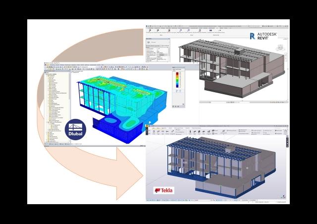
This article discusses the most common BIM interfaces. Adjustments are often necessary during the transition to the structural branch-specific model. The tasks that arise and the tools to address them successfully and quickly are presented.
![[Edit Parameters] Button in Table Toolbar](/en/webimage/009362/2418341/01-en-png.png?mw=640&hash=c76563b459152b19c98197ea6ba342be89d9a5bc)
The SHAPE‑THIN stand-alone program determines the characteristic values and stresses of any thin‑walled cross‑sections. Graphic tools and features allow for modeling complex cross‑section shapes. In addition to the graphical input, it is also possible to enter the data in tables. As an alternative, you can import a DXF file and use it as a basis for further modelling. Also, each cross-section can be entered using the cross-section library of Dlubal Software and combined as a part with the user-defined elements.
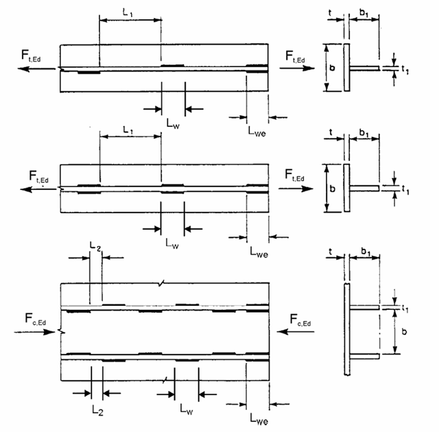
If crane runway girders are designed with flat steel rails, the welding of these rails is always a detail for the design. You can generally select between continuous and intermittent fillet welds as a rail fixing. The following article provides an overview of the design processes and their specific features, especially when using the EN 1993-6.